Costco tamales offer a convenient‚ flavorful option for quick family meals․ Their pre‑made masa and fillings allow you to enjoy authentic Mexican taste without the long prep․ This guide shows how to steam or microwave them‚ ensuring a warm‚ moist result every time․ Pair with fresh cilantro lime t zest․
Overview of Costco Tamales
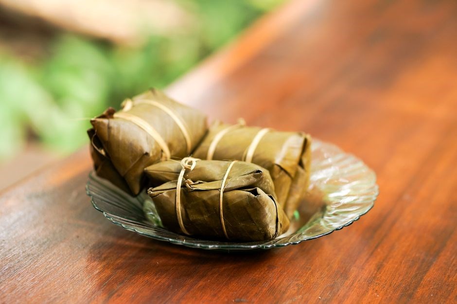
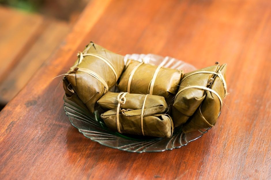
Costco’s tamales are a staple for quick‚ flavorful meals․ Packaged in foil‑wrapped bundles‚ each tamale contains seasoned masa dough filled with pork‚ chicken‚ or vegetarian․ The brand emphasizes fresh ingredients and authentic Mexican flavors‚ making them convenient for family gatherings or weekday dinners․ Costco offers seasonal varieties—red salsa‚ green salsa‚ mole‚ and holiday flavors like pumpkin for Thanksgiving․ The tamales are pre‑cooked‚ so reheating is all that’s needed‚ either in a steamer or microwave․ The simplest method is to steam 15–20 minutes or microwave on medium for 3–4 minutes․ Because the masa is already cooked‚ the goal is even reheating without drying the filling․ If a crisp exterior is desired‚ briefly toast the foil‑wrapped tamales in a skillet after steaming․ They’re also budget‑friendly for large gatherings‚ making them a smart choice for parties and family feasts today․
- Foil packaging keeps tamales fresh․
- Wide flavor range for all tastes․
- Pre‑cooked masa saves prep time․
- Large portions suit parties․
- Clear reheating instructions․
Originating from Mexico’s rich culinary traditions‚ tamales have been enjoyed for centuries․ Costco’s versions retain the classic masa made from corn masa harina‚ enriched with a touch of lard or vegetable oil for a tender crumb․ Fillings vary from savory pork seasoned with adobo to mild chicken with cilantro‚ and even vegetarian options like cheese and spinach․ Nutritionally‚ a single tamale contains roughly 200–250 calories‚ 6–8 grams of protein‚ and 3–5 grams of fat‚ depending on the filling․ They’re also budget‑friendly․
Choosing the Right Tamale Variety
Select a flavor that matches your meal: pork‚ chicken‚ or vegetarian․ Check the foil label for salsa type and spice level․ Seasonal options like pumpkin or holiday blends add excitement․ Store unopened in a cool‚ dry‚ place until ready to reheat․ Try it now
Common Flavors and Packaging Notes
Costco’s tamale line features a range of classic and seasonal flavors that cater to diverse palates․ The most popular options include pork with red or green salsa‚ chicken with mild or spicy salsa‚ and a vegetarian corn‑masa version filled with beans and cheese․ Seasonal releases‚ such as pumpkin or sweet potato‚ appear during holidays and are often sold in limited quantities․ Each tamale is individually wrapped in a foil packet that lists the salsa type‚ heat level‚ and a brief description of the filling․ The foil also indicates whether the tamale is pre‑cooked or requires steaming‚ which is essential for proper reheating․ For those who prefer a milder taste‚ the “Chicken Mild” variant offers a gentle blend of herbs and a creamy salsa; The “Pork Red Salsa” is a staple for families who enjoy a robust‚ tomato‑based flavor‚ while the “Pork Green Salsa” delivers a fresher‚ cilantro‑lime kick․ The vegetarian option is perfect for plant‑based diners and contains a hearty mix of black beans‚ corn‚ and cheese‚ providing a satisfying protein source․ When purchasing‚ check the expiration date and store the tamales in a cool‚ dry place until ready to reheat․ For best results‚ keep the foil sealed to preserve moisture․ If you plan to steam‚ place the tamales in a steamer basket and cover with a damp cloth to trap steam․ For microwave use‚ remove the foil‚ place on a microwave‑safe plate‚ and heat on medium for 90 seconds‚ then let rest for a minute before serving․ Enjoy now!!
Preparing for Cooking
Before cooking‚ gather a steamer pot‚ a heat‑proof plate‚ and a towel․ Place tamales in a layer‚ foil side up․ Fill the pot with about an inch of water‚ ensuring it doesn’t touch the tamales․ Cover tightly to trap steam during heating․
Keep pot covered to maintain steam; check water level 15 min
Essential Kitchen Tools
For steaming Costco tamales‚ a sturdy steamer basket or a pot with a lid is essential․ The basket should fit snugly inside the pot‚ allowing steam to circulate around each tamale․ A heat‑proof plate or a small tray can hold the tamales while they steam‚ preventing them from touching the pot’s bottom․ A kitchen towel or a clean cloth is useful for covering the pot to trap steam and maintain consistent heat․ A timer or clock helps you keep track of steaming time‚ ensuring the tamales are heated evenly without overcooking․ If you prefer the microwave method‚ a microwave‑safe bowl or plate with a lid will keep moisture in and prevent splatter․ A small whisk or spoon is handy for checking the moisture level of the water in the steamer‚ ensuring it stays at the right level․ Finally‚ a pair of tongs or a sturdy spoon is useful for removing the tamales from the steamer or microwave‚ allowing you to handle them safely without burning your fingers․ These tools collectively ensure a smooth‚ efficient cooking process that delivers perfectly steamed or microwaved tamales every time․ A small cutting board and a sharp knife are handy for slicing any leftover tamales or preparing fresh accompaniments like diced onions or cilantro․ If you plan to serve the tamales with a side of salsa‚ a small bowl and a spoon are essential for portioning the sauce․ For a quick cleanup‚ a silicone mat or a disposable parchment sheet placed under the steamer basket helps keep the pot tidy and reduces the need for scrubbing․ Enjoy your meal! and share with friends․ Cheers
Steaming the Tamales
Steaming Costco tamales is simple: fill a pot with 1–2 inches of water‚ place a steamer basket‚ and arrange tamales upright․ Cover tightly‚ bring to a gentle boil‚ then reduce heat and steam for 25–30 minutes․ Check moisture‚ then serve hot with salsa․ Keep the lid on to trap steam; let tamales rest a min․!
Steamer Setup and Timing
To steam Costco tamales efficiently‚ start by selecting a large‚ deep pot that can hold a steamer basket or rack․ Fill the pot with about 2–3 inches of water‚ ensuring the water level stays below the bottom of the steamer to prevent direct contact with the tamales․ Place a heat‑proof steamer basket or a rack inside the pot‚ arranging the tamales upright and slightly spaced to allow steam circulation․ Cover the pot with a tight‑fitting lid; a silicone lid or a second pot lid works well․ Bring the water to a gentle boil‚ then reduce the heat to maintain a steady‚ low simmer․ Steam the tamales for 25–30 minutes‚ checking periodically to ensure the water hasn’t evaporated․ If the water level drops‚ add a few more tablespoons of hot water․ After steaming‚ remove the pot from heat‚ let the tamales rest for a minute‚ then carefully lift them from the steamer․ They should be hot‚ moist‚ and the masa should cling to the corn husk․ Serve immediately with your favorite salsa or a squeeze of lime for an authentic touch․ For best results‚ pre‑warm the tamales by placing them in a bowl of warm water for 10 minutes before steaming; this helps them heat evenly․ If you prefer a crispier husk‚ lightly toast the husks on a dry skillet before wrapping․ Keep the lid closed during steaming to trap steam; opening it too often can lower the internal temperature and extend cooking time․ Once done‚ you can reheat leftover tamales in the microwave or oven‚ but steaming preserves the original texture․ Remember to discard any excess water after steaming to avoid sogginess․ Enjoy the rich‚ savory flavors that Costco’s ready‑made tamales bring to your table․ If you’re cooking a large batch‚ consider using a double steamer or a steamer basket with a perforated bottom to ensure even steam distribution․ Also‚ keep a small bowl of warm water nearby to rehydrate husks that dry out during the steaming process․ Finally‚ garnish with chopped cilantro‚ diced onions‚ and a drizzle of crema for a modern twist․ By mastering these steaming steps‚ you’ll consistently deliver restaurant‑quality tamales at home‚ impressing family and friends alike․ Enjoy the aroma of freshly steamed masa․
Common Steaming Issues
When steaming Costco tamales‚ several pitfalls can compromise texture and flavor․ The most frequent problem is a soggy husk: if the corn wrapper is not fully hydrated before wrapping‚ steam can seep through‚ leaving a wet‚ mushy exterior․ To avoid this‚ soak husks in warm water for at least 30 minutes‚ then pat dry․ Another issue is uneven cooking; placing tamales too close together blocks steam flow‚ causing some to steam longer than others․ Arrange them with a small gap and rotate halfway through the cycle․ Over‑steaming can also occur‚ especially if the pot’s water level rises too high․ The tamales will become rubbery and the masa will separate from the husk․ Maintain a low simmer and monitor the water level‚ topping up with hot water as needed․ A common mistake is using a pot that is too shallow; this forces the tamales to sit in the water‚ which can result in a soggy base․ Use a deep pot with a steamer basket or rack to keep them above the liquid․ Finally‚ some users report that the tamales lose their aroma after steaming․ This is often due to a lid that does not seal tightly‚ allowing steam to escape and carry volatile oils away․ A silicone lid or a second pot lid can improve retention of flavor․ By addressing these issues—hydrating husks‚ spacing‚ controlling temperature‚ and sealing the lid—you’ll consistently produce moist‚ flavorful tamales that showcase Costco’s quality
By mastering these common pitfalls‚ you’ll enjoy perfectly steamed tamales that retain their authentic flavor and satisfy all craving
Microwave Option
For a quick fix‚ unwrap the husk‚ place the tamale on a microwave‑safe plate‚ cover with a damp paper towel‚ and heat on 700W for 2–3 minutes․ Flip halfway‚ then steam for 30 seconds․ Check for warmth; repeat if needed․ This preserves moisture without overcooking․Enjoy!andshare․
Power Settings and Duration
When reheating Costco tamales in a microwave‚ the key variables are power level and cooking time․ Most household microwaves operate at a maximum of 1000 W‚ but using the full power can cause the masa to dry out or the filling to overcook․ A moderate setting of 70 %—roughly 700 W—provides a gentle heat that preserves moisture while still warming the tamale evenly․ Begin by placing the tamale on a microwave‑safe plate‚ ensuring it is not stacked or touching the walls of the microwave cavity․ Cover the tamale with a damp paper towel or a microwave‑safe lid; this traps steam and prevents the husk from cracking․ Set the timer for 2 minutes on the chosen power level․ After the first interval‚ pause the microwave‚ flip the tamale‚ and re‑cover it․ Continue cooking in 30‑second increments until the internal temperature reaches at least 165 °F (74 °C)․ If the tamale is larger or thicker than the standard size‚ add an extra 30 seconds for each additional centimeter of thickness․ For tamales that have been frozen‚ increase the total cooking time by 1–2 minutes‚ but still monitor the interior temperature to avoid overcooking․ When the tamale is thoroughly heated‚ remove it carefully—use oven mitts if it is hot—and let it rest for 1 minute․ This brief rest allows steam to redistribute‚ ensuring a uniform texture․ Quick flip gives crust․! If you prefer a slightly crisp exterior‚ you can finish the tamale in a hot skillet for 1–2 minutes after microwaving․ Finally‚ always check the tamale’s center with a food thermometer; a safe and delicious result is achieved when the core reaches the recommended temperature․
Serving Ideas
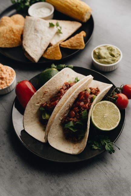
Pair tamales with fresh pico de gallo‚ a squeeze of lime‚ and a side of warm corn tortillas․ For a modern twist‚ serve them atop a bed of cilantro‑lime rice‚ drizzle with chipotle crema‚ and garnish with sliced avocado and radish slivers․ Enjoy with a side of guacamole․ Fresh!!!
Traditional Sides and Modern Pairings
When serving Costco tamales‚ classic accompaniments such as warm refried beans‚ corn salsa‚ and a bright lime‑citrus slaw bring out the masa’s subtle sweetness․ A simple side of sautéed onions‚ garlic‚ and fresh cilantro adds depth‚ while a drizzle of homemade mole sauce elevates the dish to gourmet status․ For a modern twist‚ pair tamales with a quinoa‑based pilaf infused with roasted poblano peppers and a splash of lime juice․ A side of avocado crema‚ made by blending ripe avocado‚ sour cream‚ lime zest‚ and a pinch of smoked paprika‚ offers a creamy contrast that complements the chewy texture․ A crisp lettuce salad tossed with diced mango‚ toasted almonds‚ and a honey‑mustard vinaigrette provides a refreshing counterpoint․ Add pickled jalapeño slices and toasted sesame seeds for heat and crunch․ A side of roasted sweet potato cubes tossed in cumin and chili powder delivers a sweet‑spicy balance that pairs beautifully with the tamale’s savory profile․ Mexican street corn‚ slathered in mayo‚ cotija cheese‚ and chili flakes‚ offers a smoky‚ creamy element․ A cucumber and tomato salad with olive oil and sea salt gives a crisp‚ refreshing contrast․ For a contemporary pairing‚ serve tamales with a bowl of miso‑infused broth‚ letting diners dip or sip for an interactive experience․ The combination of textures—from tender masa to crunchy toppings—creates a memorable meal that satisfies both traditional and adventurous palates alike․ Pair the meal with a chilled glass of Mexican lager or a sparkling agua fresca for a festive touch that rounds out the flavors beautifully and crisp refreshment Enjoy!!․
Storage and Reheating
Store cooked tamales in an airtight container in the fridge for up to 3 days․ For longer storage‚ freeze individually wrapped tamales; thaw overnight before reheating․ Reheat by steaming 5–7 minutes or microwaving 2–3 minutes on high․ Serve hot with fresh salsa․ Keep wrapped in foil for extra moisture․
Keeping Tamales Fresh and Easy Reheat
Keeping tamales fresh and easy to reheat is essential for preserving flavor and texture․ After cooking‚ let the tamales cool to room temperature‚ then wrap each individually in parchment paper or foil․ Place the wrapped tamales in a resealable plastic bag or airtight container․ Store in the refrigerator for up to three days or freeze for up to two months․ When ready to reheat‚ remove the parchment or foil‚ and steam the tamales for 5–7 minutes or microwave on high for 2–3 minutes․ For best results‚ add a splash of water to the steaming basket or a tablespoon of water to the microwave dish to maintain moisture․ Serve immediately with fresh salsa‚ guacamole‚ or a squeeze of lime for a burst of freshness․ Enjoy them as a quick‚ satisfying meal!!
To keep tamales moist‚ avoid wrapping them in plastic that traps moisture․ Use parchment paper or a paper towel between layers․ If freezing‚ place tamales in a single layer on a baking sheet‚ freeze until solid‚ then transfer to a freezer bag․ This prevents sticking and preserves texture․
When reheating frozen tamales‚ thaw in the fridge overnight or at room temperature․ Steam them in a basket for 5–8 minutes․ For microwave‚ place a damp paper towel over the tamale and heat on medium for 1–2 minutes‚ checking distribution․
For a crisp exterior‚ finish reheated tamales under a broiler for 1–2 minutes or bake at 350°F for 5 minutes․ This adds crunch while keeping the interior tender․ Serve with salsa‚ crema‚ or sour cream!!